
Inside the Brain Box, there is a relay, which is Normally Closed (N/C) Its connects to the Pink and Grey wires. Be careful, it will tickle you if touched when the engine is running. The B/W has a voltage potential ranging up to 140V derived from the CDI unit. If the B/W is not grounded, the CDI continues and the ignition will continue to spark. The kill switch and the ignition switch stop the CDI by grounding the Black/White (B/W) wire to Earth. My CB250 has a CDI (Capacitive Discharge Ignition). Only 8 wires are used with the 9 pin plug. The Antenna and LED have their own connections. Note the Wiring Diagram has a 9 pin plug with 10 wires coming out of it.

I haven’t decided where to put it yet, but it is NOT WEATHERPROOF, and would require protection on the CB250 This is a little control box with a sensitivity adjustment trimpot on it. This is very loud, I left it disconnected until final checking of the system. Must be grounded for SPY5000 to operate properly. This is the earth wire and does not use the 9 pin plug/socket. Basically a blue indicator light that flashes to let people know your bike has an alarm. This pair of wires does not go through the 9 pin plug/socket, it has it’s own 2 pin socket. These 2 wires connect to the Orange (O) and Sky Blue (Sb) Indicator wires, and allow the SPY5000 to control the indicators, front, back and on the display panel. This wire connects to the Starter Motor Start Wire which is Yellow with Red (Y/R) and allows the SPY5000 to turn the motor over when the remote start feature is selected. THIS DOES NOT WORK WITHOUT MODIFICATION ON MY CB250. The instructions say to CUT the Black/White (B/W) wire from the ignition key switch and connect the Pink wire to the Ignition Switch SIDE of the cut, and connect the Grey wire to the other cut B/W end. These wires are part of the Ignition Kill circuit. I will describe these two wires together as they are linked. When the remote start feature is turned on, the ignition is off, so the Spy5000 feeds +12V into the ACC wire through the Brown (Br) wire. When the Ignition Switch is on, the ACC line has +12V on it, and supplies power to lights, indicators, horn, e.t.c. This is the wire which connects to the CB250 ACC (Accessory) Wire, which is Black (B) in colour. I chose to wire it to the fused side of the CB250 power supply, by tapping into the bikes RED (R ) wire after the bikes Main 20A Fuse.
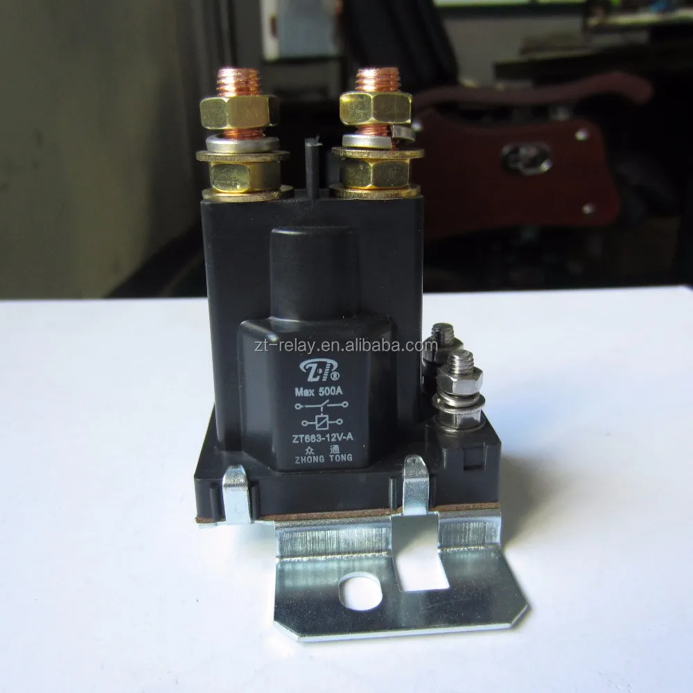
RELAY START PLUG ALARM FOR ENGINE STARTNINJA 300 MANUAL
There is an inline fuse on both sides of the plug/socket, and the manual says to wire it to the battery. This is the power supply to the BrainBox. I placed my antenna behind the rear light assembly inside the bike, as this area is mostly plastic, and it is close to the Brain Box, which is seated in the rear storage compartment. This wire doesn’t actually go through a removeable plug/socket, it comes directly out of the Brain box. As you can see in the alarm schematic, there are many wires which leave the “Brain” plug, and interface with the bike’s wiring. The Spy 5000m is a generic alarm and required modification to suit the CB250 Nighthawk.


 0 kommentar(er)
